Tool calibration is a fundamental step to ensure machining accuracy and directly affects product quality and production
efficiency. The core mechanism by which tool calibration influences machining accuracy is reflected in aspects
such as measurement error transmission, process parameter control, and the accuracy of quality inspection.
According to international standards ISO 9001 metrology technical specifications, the calibration cycle for measuring
equipment is generally 6 to 12 months, and for precision tools, it is 3 to 6 months. The measurement uncertainty of tools
should be controlled within 1/10 to 1/3 of the tolerance of the workpiece being measured, meaning the measurement
accuracy should be at least three times higher than the machining accuracy.
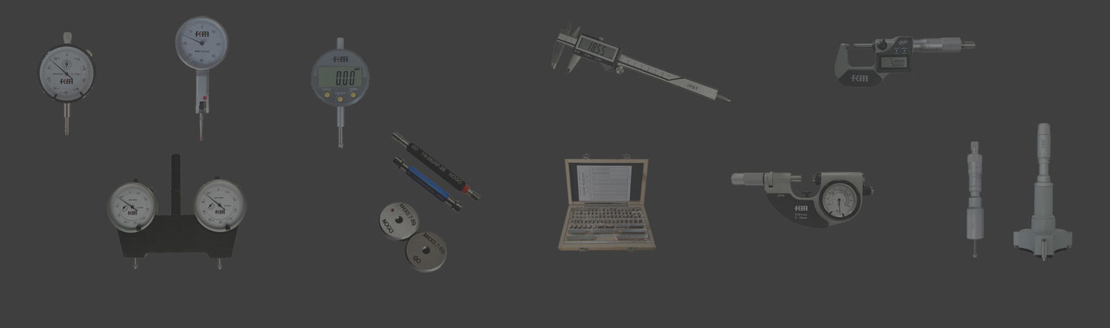
The calibration accuracy of vernier calipers is ±0.02mm, suitable for parts with IT7-IT12 tolerance grades;
the calibration accuracy of micrometers is ±0.002mm, suitable for IT5-IT8 tolerance grades;
and the calibration accuracy of dial indicators is ±0.001mm, used for IT4-IT6 tolerance grade inspections.
![]()
I. The transmission mechanism of measurement errors on processing accuracy
1. Systematic errors are the main factors affecting processing accuracy. Zero-point drift of measuring tools leads to
cumulative dimensional deviations. For example, a 0.005mm zero-point error in a micrometer will cause the same
deviation in all measurement results, directly affecting the dimensional accuracy of the workpiece.
2. Random errors affect the repeatability of measurements and the stability of processing. Random errors
caused by wear of measuring tools will lead to dispersion in measurement results, an increase in standard deviation,
and an impact on the process capability index Cpk value. Surface roughness has a significant effect on contact
measurements, and when the measured surface has a Ra value of 3.2 μm, the measurement uncertainty
increases by 50%.
Human error caused by differences in operator skills can vary by 0.005 - 0.02 mm between skilled workers
and novices. Random errors caused by external factors such as environmental vibration and air flow disturbances
need to be reduced by taking the average of multiple measurements. The control of random errors requires
the establishment of standard operating procedures, the standardization of measurement methods, regular training,
and the creation of a stable measurement environment.
3. Uncertainty evaluation is a scientific method for error analysis. Class A uncertainty is obtained through statistical
analysis and reflects measurement repeatability. Class B uncertainty is derived from calibration certificates of
standard devices, technical indicators of measuring tools, etc., and reflects systematic deviations.
The combined standard uncertainty is obtained by combining each component according to the root and method,
and the expanded uncertainty is taken as the expansion factor k = 2 corresponding to the confidence
probability of 95%. Measurement capability verification is carried out by comparing with superior standards to
confirm that the measurement system meets the accuracy requirements.
![]()
II. Precision Measuring Instrument Calibration Technical Requirements and Methods
1. The calibration of length measuring instruments adopts a step-by-step traceability system. The laser wavelength
serves as the length reference, with an accuracy of 10⁻⁹ level. The accuracy of the first-class measuring blocks
is ±0.05 μm, which is used for calibrating precision measuring instruments and measurement equipment.
The working measuring blocks have an accuracy of ±0.1 - 0.5 μm, which is used for calibrating common
measuring instruments. The caliper calibration uses a combination of standard measuring blocks to detect the
indication error at each measurement point.
The micrometer calibration needs to check the zero point, indication error, and measurement force parameters.
The standard measurement force is 5 - 10 N. The calibration environment requires a temperature of 20 ± 1℃,
a relative humidity of 45% - 65%, and no vibration interference. The calibration certificate should provide correction
values and measurement uncertainty. During the validity period of the certificate, corrections are required when using it.
2. Angle measuring instrument calibration is based on the transfer of angle reference.
A multi-sided prism serves as the angle reference, with an accuracy of up to 0.1 arc seconds. The calibration
of the sine gauge uses standard gauges in combination to test the accuracy of angle setting. The calibration of the
universal angle ruler requires checking the indication errors at each angle position, with an accuracy requirement
of ±2' to ±5'. The calibration of the level instrument tests the sensitivity and indication error, with an accuracy
of 0.01 -0.1 mm/m.
3. The calibration of shape measuring tools involves complex geometric parameters. Straightness calibration
uses laser interferometers or precision guideways to measure the deviation of the reference straightness.
Flatness calibration employs three-coordinate measuring machines or laser flatness instruments to establish
the flatness reference.
![]()
III. Application of Measuring Tools and Precision Assurance During Processing
1. The selection of measuring tools between processes directly affects the quality control of the processing.
During the rough machining stage, conventional measuring tools such as steel rulers and vernier calipers are used,
with relatively low precision requirements, and the focus is on controlling the remaining dimensions. For semi-finish
machining, precision measuring tools such as micrometers and dial indicators are employed to monitor the
changes in size trends. In the finish machining stage, high-precision measuring tools such as laser rangefinders
and three-coordinate measuring machines are used to ensure the final dimensional accuracy. The online measurement
technology integrates probe systems to achieve automatic detection during the processing, with an accuracy
of ±0.001 - 0.005mm. The probe calibration of the machine tool uses standard balls or gauge blocks to establish
an accurate relationship between the probe and the machine tool coordinate system. The automatic measurement
system can compensate for processing errors, thereby improving processing accuracy and efficiency.
2. Tool setting and alignment accuracy affect the processing dimensions. The accuracy of the tool alignment
instrument is ±0.002 - 0.005mm, which is used for the pre-setting of tool length and diameter. The laser alignment
instrument has an accuracy of ±0.001 - 0.003mm, enabling high-precision tool compensation. The contact-type probe
alignment has an accuracy of ±0.0005 - 0.002mm, suitable for precision processing. The non-contact optical alignment
system avoids tool wear and has an accuracy of ±0.001 - 0.005mm. The tool monitoring system detects tool wear in
real time and automatically compensates for size deviations. The damage detection function prevents quality accidents,
and the acoustic emission sensor monitors the tool condition. The tool life management system optimizes the tool
changing time and ensures consistent processing accuracy.
3. The positioning accuracy of the tooling fixtures is a crucial aspect for ensuring the machining accuracy.
The positioning pin holes of the fixtures have an H7 precision, and the clearance is controlled within 0.005 - 0.015mm.
The flatness of the positioning reference surface is 0.005 - 0.02mm, ensuring the stability of the workpiece positioning.
The clamping force is controlled within a reasonable range to avoid deformation of the workpiece and its impact
on the accuracy. The inspection tools for the fixtures include gauge blocks, ring gauges, platforms, square boxes,
and other specialized equipment.
![]()